2: Thursday, March 27
Today, in class, we are working to create a test circuit board using the Voltera Punk Console tutorial. We have been following the steps found online via Voltera. The goal of this is to better understand the Voltera board printer for our car project.
With this experimental test, we were able to prep the printer, outline the circuit with a probe, and have the probe calibrate the circuit board.
Having downloaded the software, we were also able to experiment with how to use this for designing our own project. We learned that this process, while long, is not too hard.
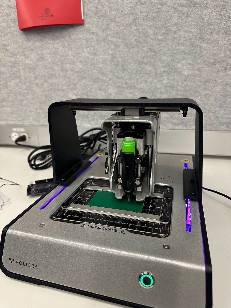
After calibrating the circuit board, the ink was calibrated and tested on the circuit board (pictured below). Considering this was just a test for the ink, we wiped off that experimental ink.

Next, in order to get the drill aspect of this process set up, we re-probed the circuit board and drilled the board corresponding to our design.

We finished class off with drilling our holes. Our product at the end of class is pictured below. Next class, we plan on finishing this circuit boarding by printing the ink on both sides.


That's really interesting! What's the test circuit board for?
Using the circuit printer is a cool idea! What is the software for this?